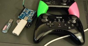
- CDi2USB first adaptator prototype
CD-i Controller Library
Arduino Library for CD-i controllers The code is released under the GNU General Public License.
Summary
This library can be used to communicate as a controller to a CD-i player.
Changelog
| Version | Date | Comments |
|---|---|---|
| v1.0.0 | 03-01-2021 | Initial Release |
| v1.0.1 | 06-01-2021 | Added experimental keyboard support, added and changed some examples |
| v1.1.0 | 23-01-2021 | Implemented serial communication using a timer instead of the SoftwareSerial library |
Table of contents
Installation
For installation see: https://www.arduino.cc/en/Guide/Libraries#importing-a-zip-library or simply place the CdiController.cpp and CdiController.h files in the sketch folder.
Library Usage
Hardware Setup
In order to communicate with the CD-i player, the controller port pins “RTS” (pin 7) and “RXD” (pin 2) need to be connected to a digital input on the Arduino board.
Software Usage
In your sketch you declare a controller using CdiController Cdi(<RTS_PIN>, <PIN_RXD>, <DEVICE_MODE>);, where you pass which pins are connected to the CD-i controller port RTS and RXD pins, as well as the device type.
The library itself is initialised by calling the CdiController.Init() function (preferable in your sketch’ setup() section. Within the loop() section of your sketch you need to call the CdiController.Task() function which handles the connection and identification to the CD-i player.
Devices
The CD-i player supports different kind of input devices. Four modes are supported by the library, passing in the correct mode to the library during declaration:
- Relative Coordinate Devices – Device Mode
RELATIVE: For example Mice, Trackballs - Maneuvering Devices – Device Mode
MANUEVER: For example Joysticks, Joypads - Absolute Coordinate Devices – Device Mode
ABSOLUTE: For example Graphics Tablets, Light Pens - Absolute Screen Devices – Device Mode
SCREEN: For example Touch Screens, Light Pens - Keyboard – Device Mode
KEYBOARD: Simple keyboard - Extended Keyboard –
EXT_KEYB: Full 104 key keyboard
Input Modes
The libary provides the following functions for transmitting data to the CD-i player:
JoyInput(x, y, button_1, button_2)For RELATIVE and MANEUVER modes. X and Y specify the relative movement since the last update, values can be between -128 and 127. Button 1 and Button 2 are boolean values indicating if these buttons are depressed or not.PenInput(x, y, button_1, button_2, pen_down)For ABSOLUTE and SCREEN modes. X and Y specify the absolute location of the cursor on screen, going from 0 (Outermost left, top of the screen) to 1023 (Outermost right, bottom of the screen). Button 1, Button 2 and Pen Down are boolean values indicating if these buttons are depressed or not.
For all of these functions a boolean value is returned indicating if data has actually been sent to the CD-i player.
Examples
Most of the examples make use of an USB Host Shield (https://chome.nerpa.tech/arduino_usb_host_shield_projects/) to use a controller as input, then converting this to a CD-i joystick. The following examples are included:
- AnalogStick: Uses an analog stick connected to the analog inputs of the Arduino as input for a CD-i Maneuvering Device. Clicking the stick serves as button 1.
- MagicNS: Uses a controller (for example Switch SNES or Switch Pro) connected to a Magic NS adapter, connected to a USB Host Shield as input for a CD-i Maneuvering Device. Both the left stick and d-pad are mapped to movement. With the left/right triggers a speed can be selected.
- USBKeyMouse: Uses a Keyboard and/or Mouse connected to the USB port of a USB Host Shield as a CD-i Relative Coordinate Device. The mouse is mapped as expected, for a keyboard the directional keys are mapped to movement, ‘Z’ is mapped to button 1 and ‘X’ is mapped to button 2. The number keys (0-9) can be used for speed selection.
- WiiController: Uses a WiiMote or Wii U Pro controller connected to Bluetooth adapter, connected to a USB Host Shield as input for a CD-i Maneuvering Device. Both the left stick and d-pad are mapped to movement. With the plus/minus buttons a speed can be selected. It assumes a sideways orientation for a WiiMote (D-pad left, buttons 1 and 2 to the right).
- WiiLightGun: Uses a WiiMote connected to a Bluetooth adapter, connected to a USB Host Shield as input for a CD-i Absolute Coordinate Device. It uses the IR mode of the WiiMote, which needs to be enabled in the ‘settings.h’ file for in the USB Host Shield Library. Use button ‘1’ and ‘2’ to enable and disable IR Mode. Button A and B on the WiiMote are mapped to buttons 1 and 2 on the CD-i.
- WiiUProAbsolute: Uses a Wii U Pro controller connected to Bluetooth adapter, connected to a USB Host Shield as input for a CD-i Absolute Coordinate Device. The range of the left stick is mapped to the full screen, the right stick provides a smaller offset for fine tuning.
Comments
Communication is now implemented using a timer/interrupts. This fixes the issue with The Apprentice (which expects 100% serial line usage) and makes it run smoother in other games as well.
Known Issues
ToDo
- Document and test CD-i Keyboard support
- Test two player support using a single Arduino
THANKS
This project is a work of TwBurn (The World of CD-i member) USB2CDi project.
It is still under development for better compatibility with the already working accessories and future USB devices.
His work is also available at GitHub.
You can comment on this page, our on the Forum topic.
##############################
Let’s make your USB 2 CD-i
IMPORTANT NOTE:
You will need to use this compilation of Arduino Sketches in conjunction with this CD-i Controller Library.
https://github.com/TwBurn/usb2cdi
This page describes how to build an USB to CD-i convertor using the CD-i controller library.
Materials
- Arduino Pro Micro 3.3v
- USB Host Shield Mini
- Logic Level Shifter (4 pin)
Schematic
The schematic above shows how you need to connect everything. The pins of the Arduino Pro Micro line up with the pins of the USB host shield, so you can use headers to solder them on top of each other. However:
- The reset pin of the USB host shield lines up with a GND pin on the Arduino, this one needs to be connected to VCC instead.
- By default the VCC is hooked up to the VBUS of the USB connector, which is 3.3V. Most USB devices will work on 3.3V, but in order to get 5V on the VBUS, you need to cut a trace on the board (indicated in the schematic) and hook up the VBUS pad to the RAW pin on the Arduino.
Both of these can be done by soldering two wires on the back of the USB Host shield.
The Logic Level Shifter is needed to convert the 3.3V signals of the Arduino to the 5V which is used by the CD-i player. The pin connections listed in the schematic are made in a way that supports two controllers at once (integrated splitter).
When built in this way the example sketches can be run without any alterations.
Alterations
Compact Design
In order to create a very compact version, I’ve soldered the Logic Level Shifter (rotated 180 degrees from the schematic) on top of the Arduino Micro, connecting all six pins (LV1 to LV4) to digital outputs on the Arduino (pins 2 to 7) – connecting “LV” to pin 4, and “GND” to pin 5. This does require an alteration to the sketches, namely the following code needs to be added to the top of the setup() function:
pinMode(4, OUTPUT);
pinMode(5, OUTPUT);
digitalWrite(4, HIGH);
digitalWrite(5, LOW);
This configures pins 4 and 5 as output, and provides 3.3V on pin 4 and ground on pin 5.


Hello,
i can’t buy this anymore? https://cdibluetooth.com/